Effect of Planning Depth in Predator-Prey Behavior
Northwestern University: Final Project
Technical Skills Used
- CAD (Solidworks)
- Laser Cutting
- Python
- ROS
- OpenCV
- 3D Printing
Hardware
- Two Sphero Mini Robots
- Two Microsoft LifeCam Studio Cameras
- Two 3D-printed camera mounts
- 1/4" and 1/8" Baltic Birch Plywood for Laser Cutting
- 80/20 for building the Camera Rig
Objectives
The goal of this project is to demonstrate the effect of prey planning-depth for reaching some goal position before the predator kills him in a 3-D honeycomb-styled-world environment with various levels of occlusion. This project breaks down into 3 different parts listed below:
- Maze Fabrication
- Sphero Control with ROS
- Image Processing to determine robot locaton in maze
The first order of business was to create the maze design since it is the playground within which the Sphero robots will be moving and from which close-loop feedback control will be implemented using image processing. Therefore, much of the Spring quarter was dedicated to accomplishing this objective.
The next order of business was to develop the code that would implement the close-loop feedback control of the Spheros using image processing. This took place during the following Fall quarter.
Maze Fabrication
In considering the design of the maze, certain specs and constraints had to be considered which are listed below:
- The maze needs to incorporate honeycomb-styled cells (since a honeycomb network is derived from nature)
- Each side of the hexagonal cell must be big enough to allow a Sphero to pass through it
- The maze at its widest should be 17 cells across
- The maze should be octogonal in shape
- The occlusions should be able to withstand collision from the Sphero robots
- The occlusions should be able to be removable from the maze
- The occlusions should be able to be placed on any cell within the maze
- There should be walls around the maze to contain the robots
- The robots should be able to move from cell to cell within the maze without significant disturbance from the ground structure
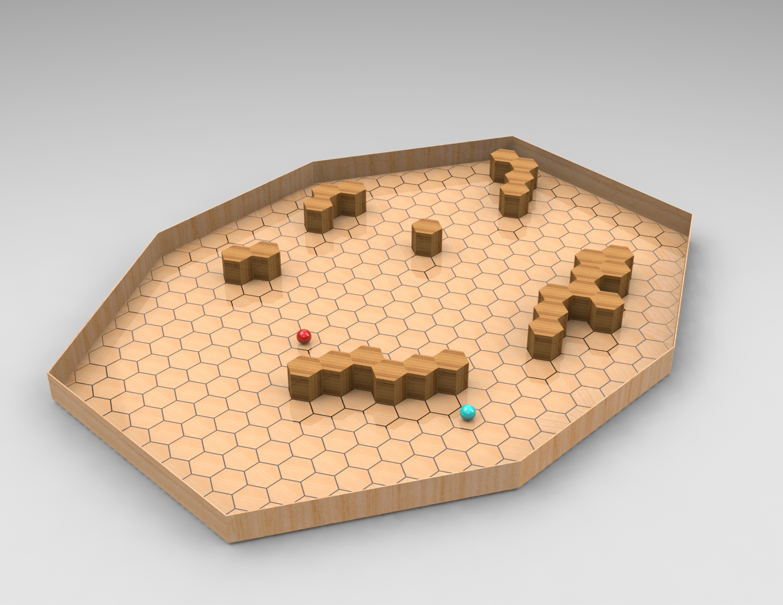
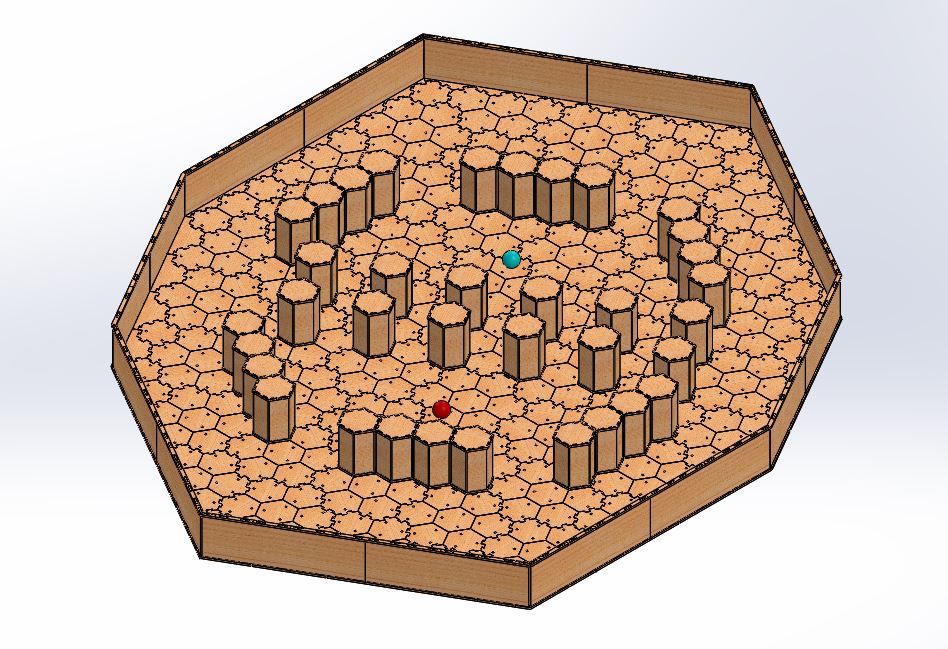
With all of these design considerations in mind, an inital rough assembled model was cadded which is shown below:
Before building the full blown model, it was decided to first build a small scale version so that initial testing could be done with the Sphero control and Image Processing algorithms. Any modifications to the structure due to testing could then be incorporated into the full-scale model.
Small Scale Model
The small scale structure, both model and actual are shown side by size below. This Readme goes through each part in the assembly and explains its purpose.
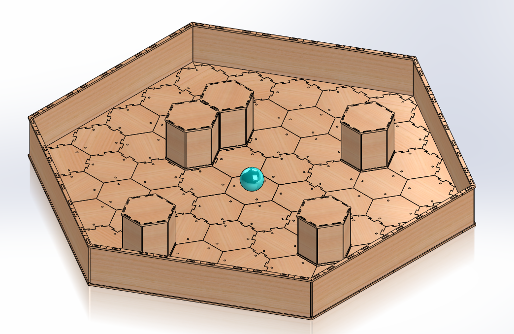
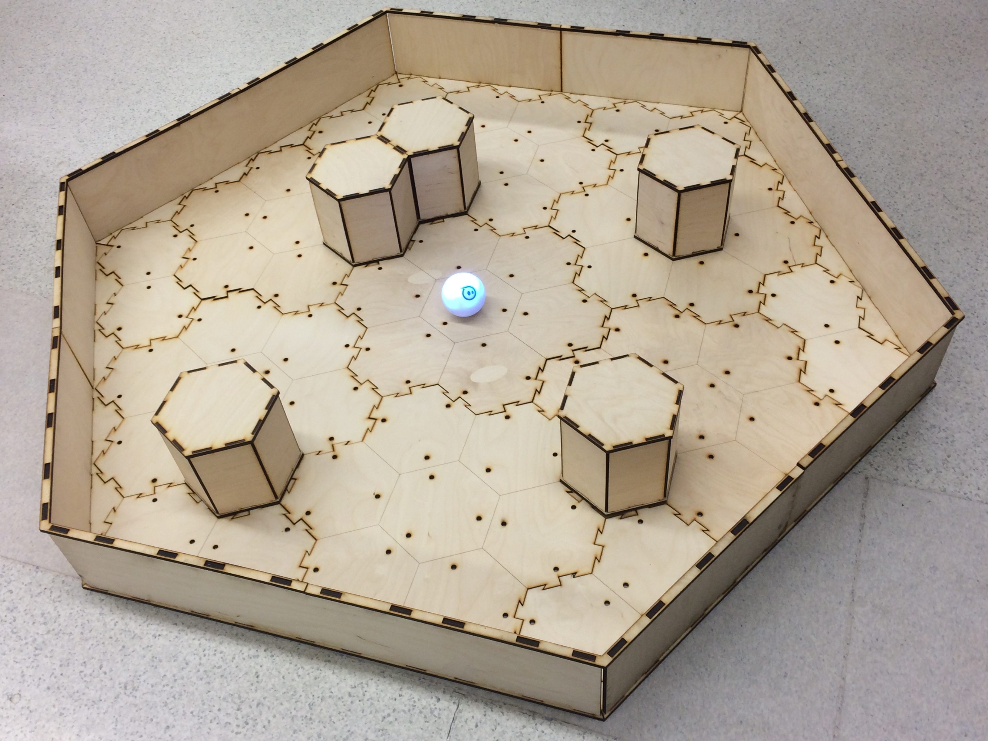
As can be seen from the pictures above, the idea was to make the maze structure modular. This allows setup and breakdown to be much easier and also allows for various maze sizes to potentially be constructed if desired. Furthermore, each moduler floor piece can be interconnected with its neighbors seculerly by using a jigsaw puzzle scheme inspired from this laser cut Settlers of Catan game.
Much thought went into deciding how to approach the obstacle dilema. In order for the obstacles to be seculerly in place on the board, it would logically make sense to have some sort of hole structure on the floor modules. On the flipside, having holes in the floor could potentially cause significant disturbances to the Sphero robots as they roll on the floor. As such several ideas were generated which are listed below:
- Using really small dowel pins (1/16 inch) so that the holes would be so small so that it would be almost negligible to the rolling trajectory of the robot
- Using 1/4 inch diameter magnets that would sit in the holes flush with the surface but would at the same time hold an obstacle (with the opposite magnets on its bottom side) to the board if placed there
- To use bigger diameter holes, but to implement some sort of plug that will fill in all holes not beeing occupied by obstacles
The issue with the first idea was that it was almost impossible to align the pins from the obstacle to the holes on the floor due to such a small tolerance. The second idea would fix this issue because of the magnetic pull between the obstacle and floor, however, there was no gaurantee that the magnets would not fall out after much use, even if glued in, due to their smooth exterior, and whether they would provide sufficient force to hold the obstacle in place should the robot crash into it at full speed. Even if higher strength magnets would be used, there would need to be some layering to be done to prevent them from popping out of their holes which adds to the complexity of the design. Finally, the magnetic force could also potentially cause disturbance to the magnometer on the Sphero (if one is in there), which would not be good at all. The last idea could potentially work, but then we run into the issue of the plugs not being exactly flush with the board, and the fact that there would still need to be a way to unplug the plugged holes.
As it turned out after testing, 1/4 inch diameter holes did not disturb the rolling motion of the Sphero robot at all, so 1/4 inch dowel pins were used to plug in the obstacles. It should also be noted that minor warping in the wood also did not affect motion of the Sphero so even small bumps from where one module connects to the other were negligible in being manifested in the robots motion. A picture of these pins attached to the obstacle is shown below:
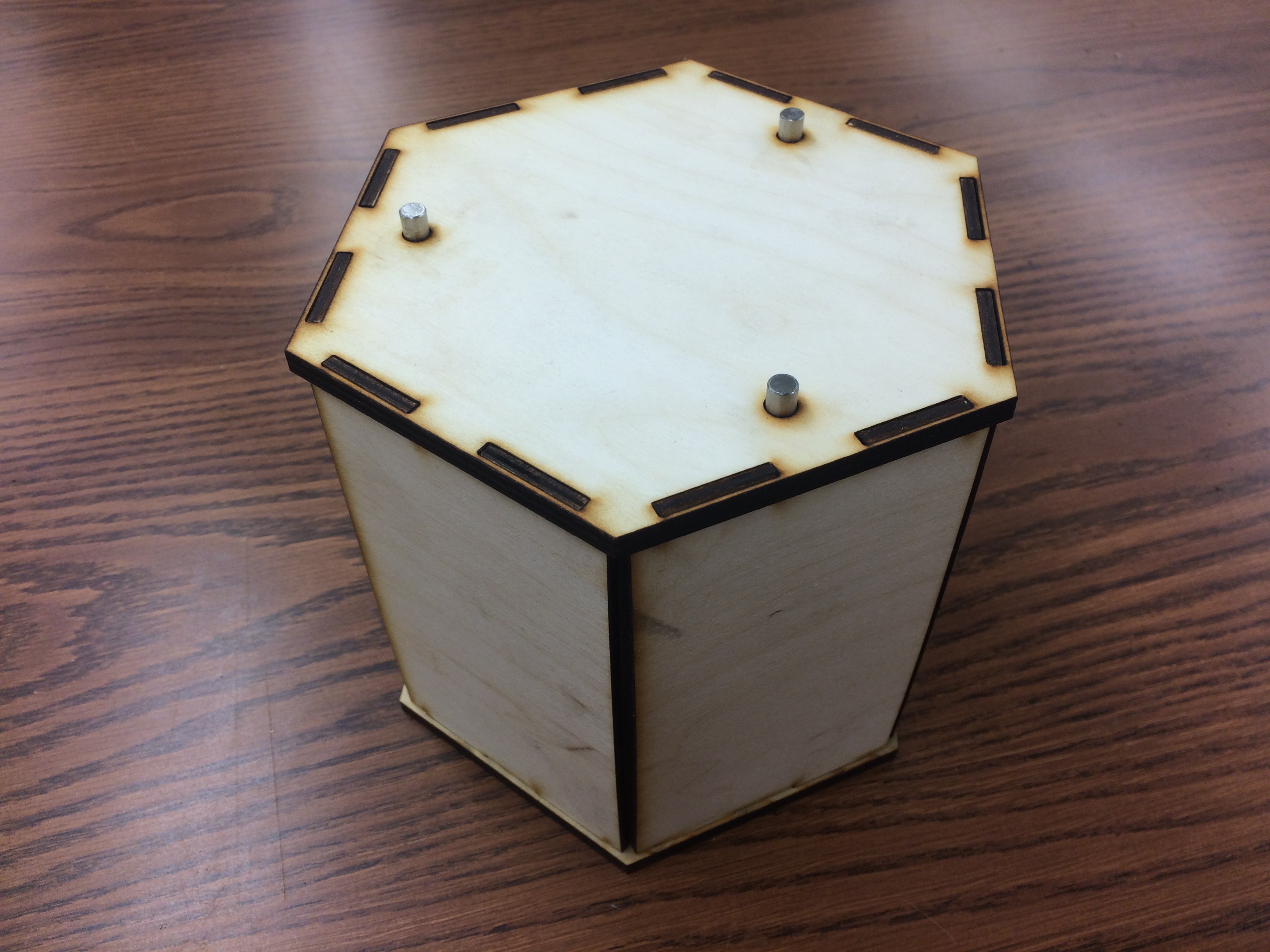
The obstacles were made with a hollow press-fit design in order to conserve wood. A wood backing was glued on the opposite side of where the holes are located in order to prevent the dowels from being pushed through into the hollow interior.
Full Scale Model
The full scale structure, both model and actual are shown side by size below. This Readme goes through each part in the assembly and explains its purpose.
Based on testing on the small-scale maze and for space constraint reasons, some modifications were done for the full-scale maze. These include:
- Making the full scale maze smaller. Initally, it measured around 11ft by 8.6ft which was too big for any space at Northwestern long term. Rather than minimizing the number of cells within the maze, each hexagonal cell was made smaller by changing each side dimension from 3.5 inches to 2.5 inches. This resulted in the full scale maze being 8ft x 6.25ft which fits snugly within the corner of Professor Maciver's lab. All modules were updated accordingly.
- Using Sphero Mini Robots instead of the Sphero 2.0 Robots since the 2.0 ones were too big.
- Laying a clear vinyl mat on the maze floor in order to make it one continous surface. This became necessary since after switching to the Sphero Mini robots, they sometimes got stuck due to discontinuous surfaces at the modular connection points due to module warping of the wood.
Sphero Control with ROS
Before knowing that I was going to switch to using the Sphero Mini, all control with the Sphero 2.0 robots were done with the sphero_ros package developed first by Melonee Wise and then further developed in the Murphey Lab. In order to control 2 robots simultaneously, I created my own fork as I had to do some modifications to the sphero.py node that would allow me to connect to specific bluetooth addresses. The Sphero Ros API provided by Melonee Wise was also helpful in regards to knowing how to talk to the Sphero 2.0 robots. It should also be mentioned that the Sphero 2.0 robot was originally chosen instead of the more recent Sphero SPRK+ due to the fact that it's hackable as mentioned in the "Tech Specs" tab here and because there seems to be an issue connecting to the SPRK+ as discussed here.
One main disadvantage to switching to the Sphero Mini robots was that the sphero_ros package was incompatible with them. Luckily, an unofficial API was created for them by MProx which proved to be just what I needed to control them. Occasionally, there are bluetooth connection problems that I discuss in my Readme and there were some modifications I had to make to his library in order to allow for simultaneous control of 2 robots, but the API works well overall. A nice advantage of using the Sphero Mini robots though is the fact that they have much less inertia than the Sphero 2.0 robots. This means controlling them along a path is more fluid than for the 2.0 robots. On the flipside, they have a greater tendency to get stuck at discontinuities due to module warpage between connection points, but the vinyl mat should take care of that.
To demonstrate the differences of controlling the Sphero 2.0 and Sphero Mini robots, take a look at the gifs below. The first set shows control of 2 Sphero 2.0 robots along their respective paths. Note how they oscillate somewhat as they follow their paths and how sharp turns can be quite a challenge for them to overcome.
Now take a look at how the Sphero Mini robots handle the sharp turns. They are much more smoother and are able to do them at a faster speed than the Sphero 2.0 robots. Hence, it seems that the advantages of the Sphero Mini robots outweigh its disadvantages all things considered.
To read more about how the spheros were calibrated and controlled, take a look at my Readme
Image Processing
In order to determine the location of the Sphero robots within the maze, computer vision feedback was used. For the small scale maze, color segmentation in the HSV space was used to isolate the contour of the maze from which a convexHull could be extrapolated using OpenCV (the green outline shown in the gifs above). Then, the 6 points of the convexHull could be determined from that which would correspond to the 6 points of the hexagonal shaped maze (the blue dots shown in the gifs above). After taking 100 samples of these points, the mode for each point was determined in order to increase accuracy of finding the right points. With these 6 points, all of the cells within the maze could be determined (shown as red dots in the gifs above).
Color segmentation in the HSV space was also used to isolate the individually colored spheros. In the gifs above, the red sphero outlined in green was considered to be the prey and the blue sphero outlined in blue was considered to be the predator.
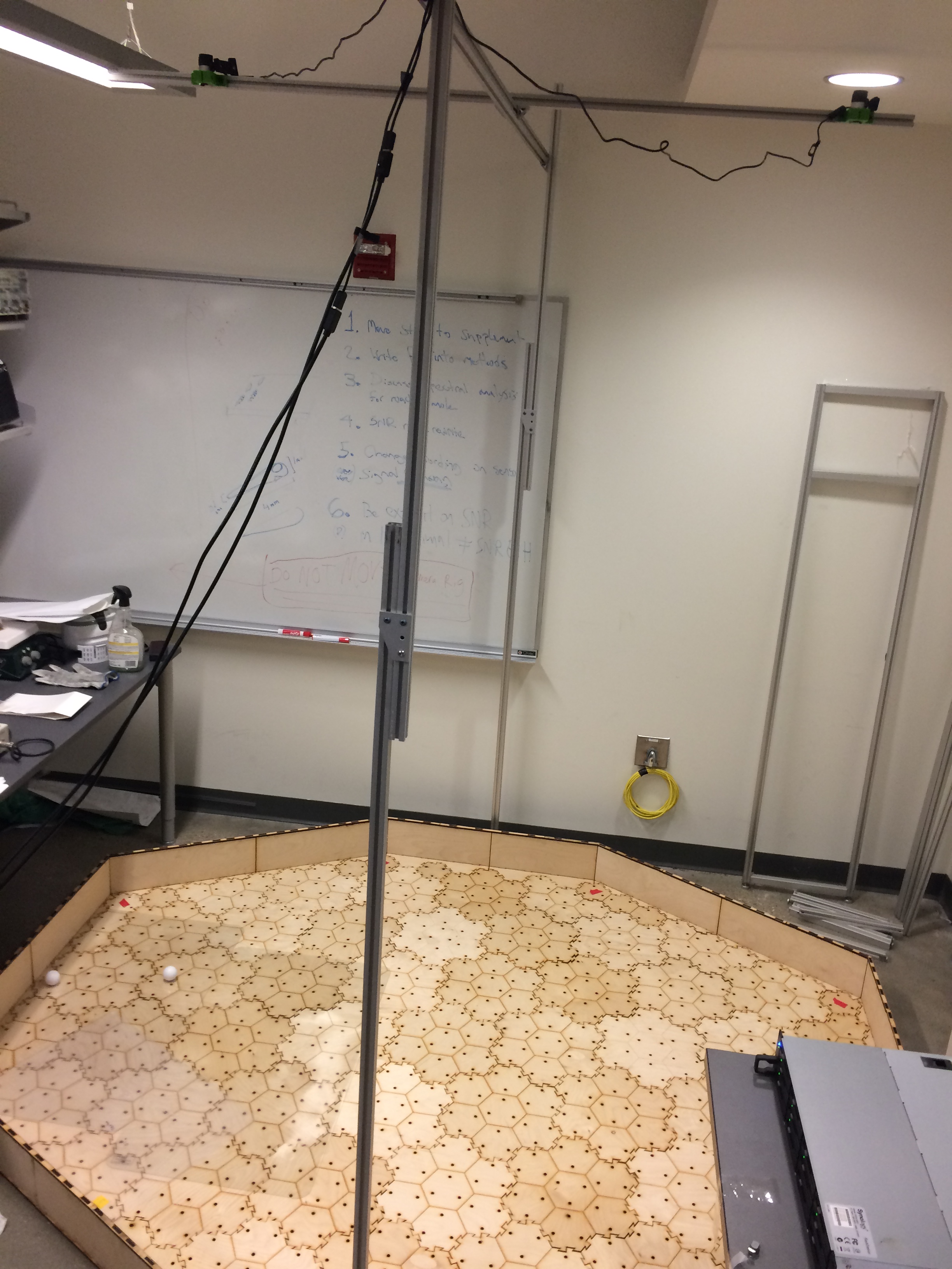
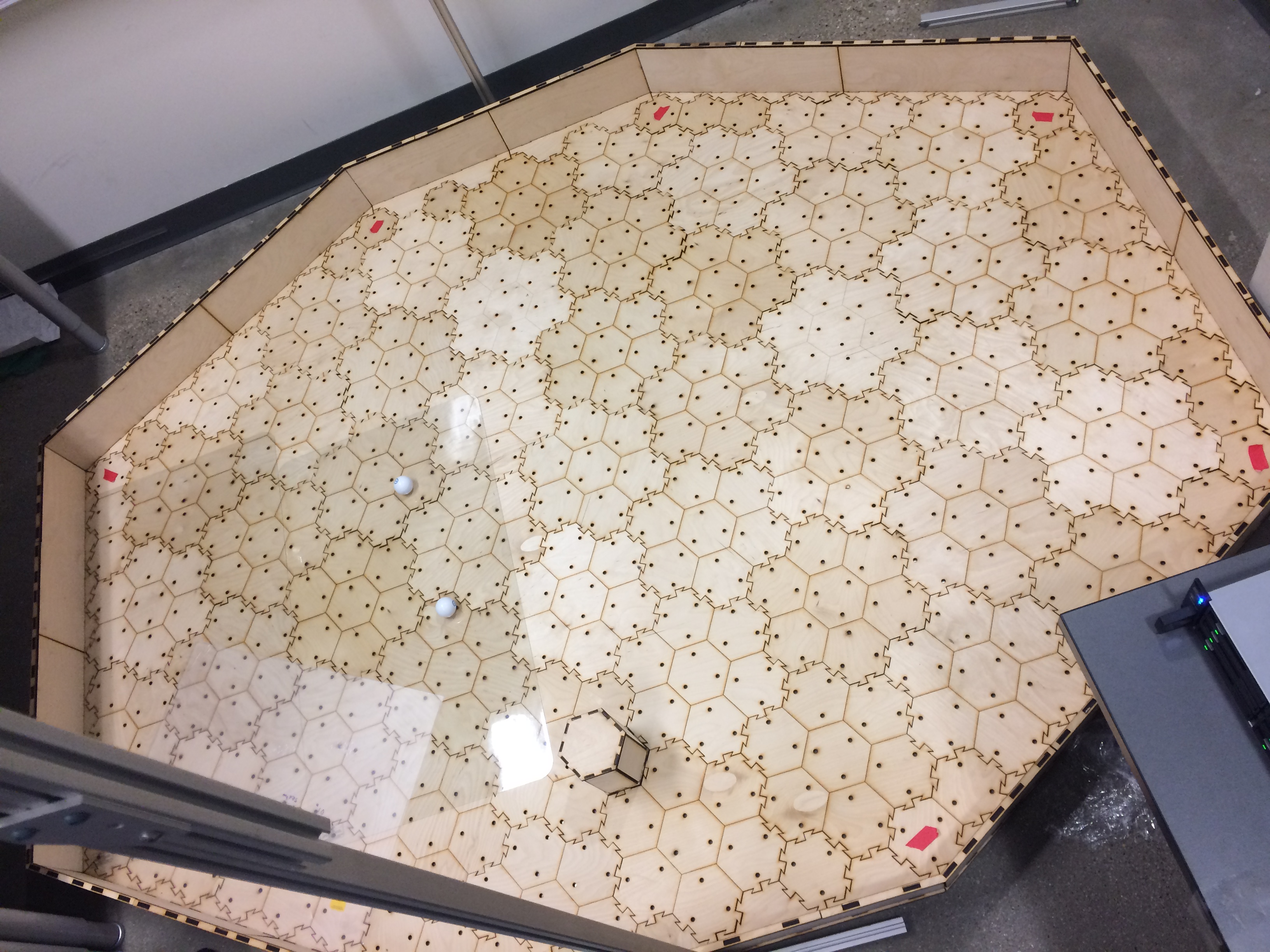
A similar approach was implemented for the full scale maze. The main difference was that instead of using the verticies of the points of the octogonal maze to inerpolate all of the other cell points, 8 pieces of red tape were placed in key locations as shown below on the left. From this, all points could be interpolated as shown in the picture below on the right. This had to be done this way since the lineup of the cells are not as symmetric in this nonregular octogonal maze as it is in the small-scale regular hexagonal maze. It is important to note that finding the contour of the maze and its correspondig vertices were still important because it allows me to segment my region of interest from whatever objects are laying outside the maze. For example, any red object outside the maze would not be considred as a red tape key location which helps eliminate false positives.
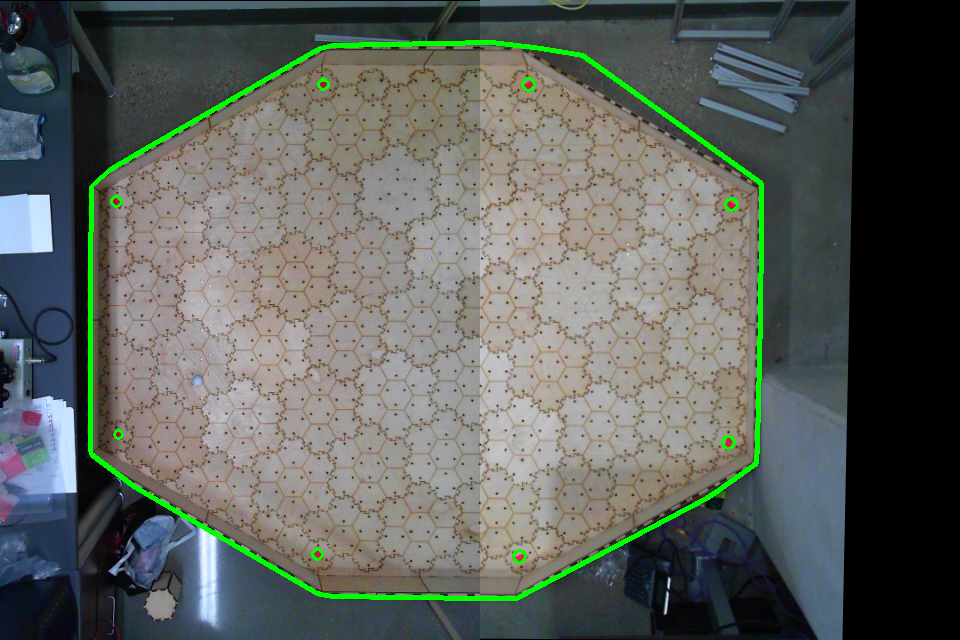
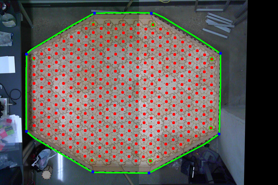
You may also notice that it looks like the images for the full-scale maze above look stitched together. You would be correct. Real-time image stitching (based off this amazing pyimagesearch blogpost by Adrian Rosebrock) was done since 2 cameras were used to visualize the maze. This was done because if one wide-angle camera was used in the center, then obstacles further along on the x and y axes from the camera would inhibit its field of view. This means that if the spheros were behind certain obstacles at the right angle, the camera would not be able to pick them up. With 2 cameras, however, any blind spots in one camera's FOV due to obstacle blockage may be picked up from the other camera. These cameras were mounted using custom made 3D-printed mounts onto a custom made camera rig made out of 80/20.
To understand more about how a user would setup all the image processing nodes as well as how to calibrate all the color segmentation parameters, read my Readme here.
Demo
A video demo of the full-scale maze is shown below. Stay tuned for a better demo with longer paths.
Future Steps
These are some future steps to implement based on how advanced the project becomes down the road such as when mice begin to be put into the maze:
- Either covering the maze with acrylic or plexiglass sheets like these sheets or increasing the height of the maze walls and obstacles in order to prevent the mice from jumping out of the maze. If the height of the obstacles are modified to be higher, then more cameras may need to be added so that any blindspots caused by the height of the obstacles in some cameras can be picked up by others.
- Adding in capability to track the path a mouse moves within the maze when chased by a sphero.
- Adding in Real-Time planning capabiliy based on scenarios modeled within the maze. When this occurs, obstacle detection will need to be added as well.