DC Motor Control
Northwestern University: Introduction to Mechatronics
Technical Skills Used
- Embedded Programming in C on the PIC32MX795F512H as configured on the NU32 development board
- Brushed DC Motor control with H-bridge, encoder, and current sensing chip
- Serial Communication between the PIC and MATLAB
- Current Sensor Calibration based on ADC counts
- PWM via Output Compare
- Interrupts and Timers
- PID Controller Design
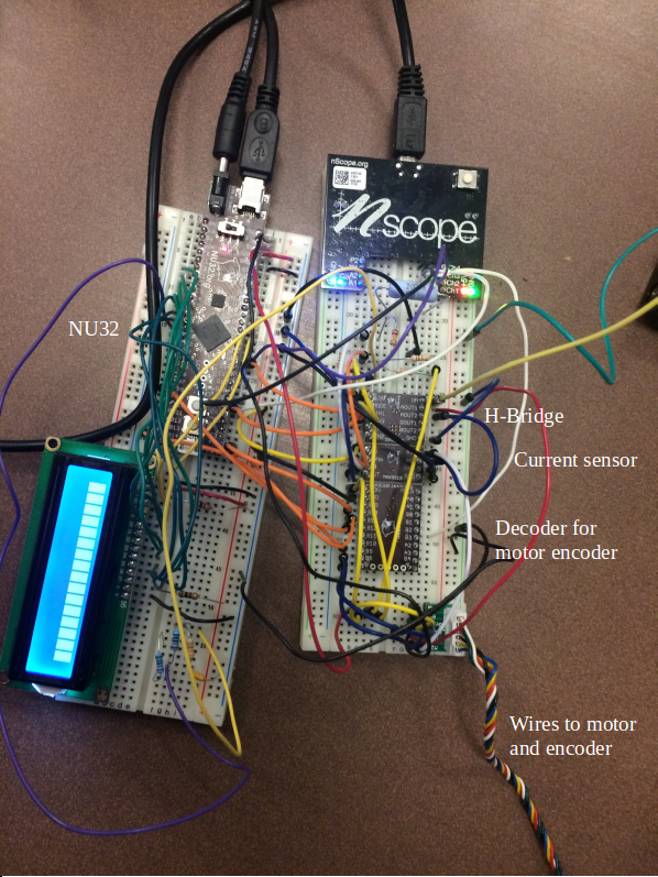
Hardware
- Brushed DC motor with encoder
- NU32 microncontroller board (with the PIC32MX795F512H)
- PCB with quadrature encoder counter chip
- connected via SPI to the NU32
- PCB with MAX9918 current-sense amplifier and a built-in 15 $m\Omega$ current-sense resistor
- provides a voltage proportional to the motor current which is received by an ADC input pin on the NU32
- PCB with the DRV8835 H-bridge
- attached to a PWM/OC channel on the NU32
- 6V Battery pack
- Various resistors and capacitors
How it Works
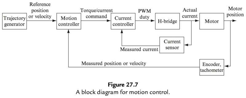
The final project for the class was to control the DC Motor such that it could track some given reference trajectory. This was accomplished by following the block diagram (taken from the class textbook) shown below. Note, all relevant code can be found in my github repo here.
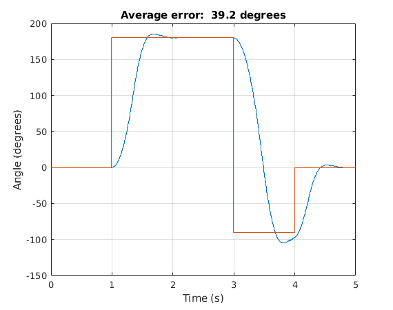
Trajectory Generator
The trajectory that the motor tracks is entered through the MATLAB client. For example, the entry [0,0;1,180;3,-90;4,0;5,0] means that at time 0 seconds, the motor angle should be at 0 degrees; at time 1 second, the motor should be at 180 degrees, and so on and so forth. The reference step input can be seen as red in the plot on the right. The actual trajectory that the motor achieved can be seen in blue. Unsurprisingly, there is a fair bit of error, since the motor has to overcome the inertia of the bar fixed onto the motor shaft.
Motion Controller
As can be seen from the above block-diagram, once the trajectory is entered through the MATLAB client, it is sent to the motion controller on the PIC32 over UART serial communication. The motion controller (which is running at 200 Hz in an interrupt) reads the current motor position from the encoder over SPI, converts that position into its corresponding angle (based on the number of ticks on the encoder and its quadrature nature), and compares it against the reference angle in the provided trajectory to get the angle error. PID control is then implemented using this error to output a reference current that should be tracked by the current controller so that the right amount of current is going through the motor terminals. After some tuning, the following gains were used (at least for tracking the step trajectory): $K_p=5$, $K_i=0$, and $K_d=200$.
Current Controller
Moving onward in the block-diagram, the current controller takes the reference current provided by the motion controller and compares it to the current read from the current sensor to get the error. As hinted in the hardware section, the current sensor works by measuring the voltage drop across a 15 $m\Omega$ current-sense resistor which is then amplified using the MAX9918 current-sense amplifier. This allows the voltage (which is proportional to the motor current) to be read by the ADC input pin on the NU32. In order to determine the relationship between the ADC count and current, a "calibration equation" was generated through testing of the current sensor with known currents that would likely be experienced for various loadings of the motor.
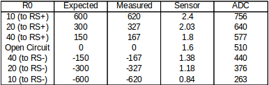
These currents were achieved by using combinations of one or two 20 $m\Omega$ power-resistors either in parallel or in series. The current and voltage was measured in each scenario by using an ammeter and oscilliscope. If those values checked out, then the ADC counts were measured by the NU32 in each of those scenarios which then tells us the relationship between ADC counts and current. The table with all of of these values can be seen right above. The equation determined was $Current=2.5(ADC)-1273.16$.
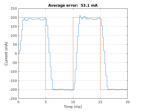
Anyway, with the current error known, another PID controller (this one running at 5 kHz) is implemented and outputs a PWM duty cycle that changes the voltage across the motor terminals (which thereby changes the current going through the motor) so that the reference current outputted from the motion controller earlier can be achieved. In order to determine some good gains for this controller, a 100 Hz $\pm$200mA reference current (shown in red in the above plot) was attempted to be tracked. The actual current trajectory is shown in blue. The gains determined were $K_p=1$, $K_i=0.05$, and $K_d=0.83$.
It should be noted that the PWM frequency controlling the voltage across the motor via the H-bridge (as described in the block diagram) was running at 20 kHz.
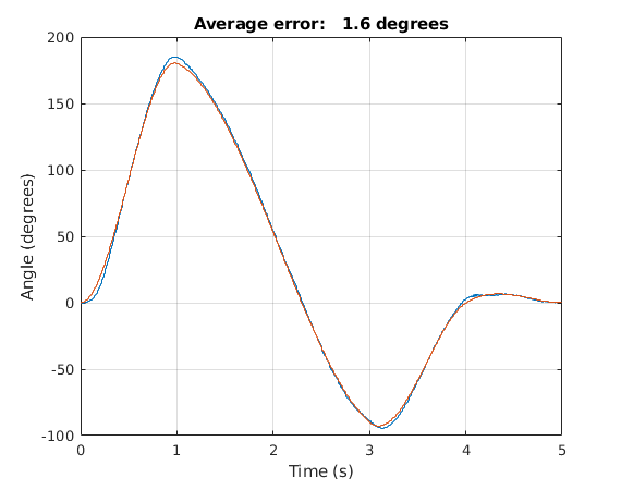
Demo Video
A demo video of the DC Motor tracking cubic trajectories. The first one shown in the video is with bad PID gains, whereas the second attempt is with good PID gains. An example plot of the requested and desired trajectories are shown on the right. You may notice how the average error is much smaller than for a step trajectory input. This is because the changes in a cubic trajectory are more gradual whereas by a step input, they are instant. The gains used for this cubic trajectory were: $K_p=20$, $K_i=0$, and $K_d=200$.